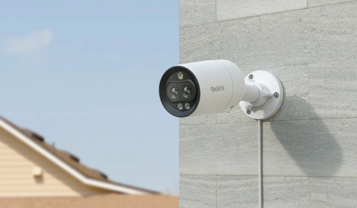
I’m switching from Eufy to Reolink IP/security camera’s. Mainly because of their more than excellent integration in HomeAssistant, my home automation platform of choice.
Since I recently also upgraded my home network to Ubiquiti and with that the ability to use PoE I bought my first PoE camera since the idea of running just one, single cable for both network connectivity and power seemed nice. Two other camera’s here at home are WiFi based.
Now when I received the camera (a RLC-81MA 4K/8MP dual lens model) I was a bit disappointed when I saw the ugly, bulky and short splitter cable Reolink included and worse: it was not detachable! These were BTW not visible in the Reolink marketing material. I actually bought a Ubiquiti ultra thin ethernet cable for it, thinking I would be able to plug it into a RJ45 connector -on- the camera.
Oh well, so what does a tinkerer/hacker do next? Right, screw a brand new camera open and “fix it”! 😂
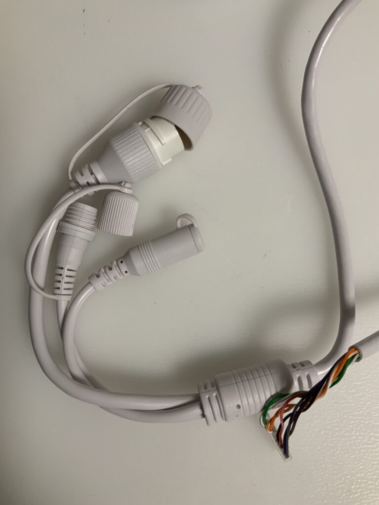
Inside the camera the 12 pin connector led to the cable going out of the camera.
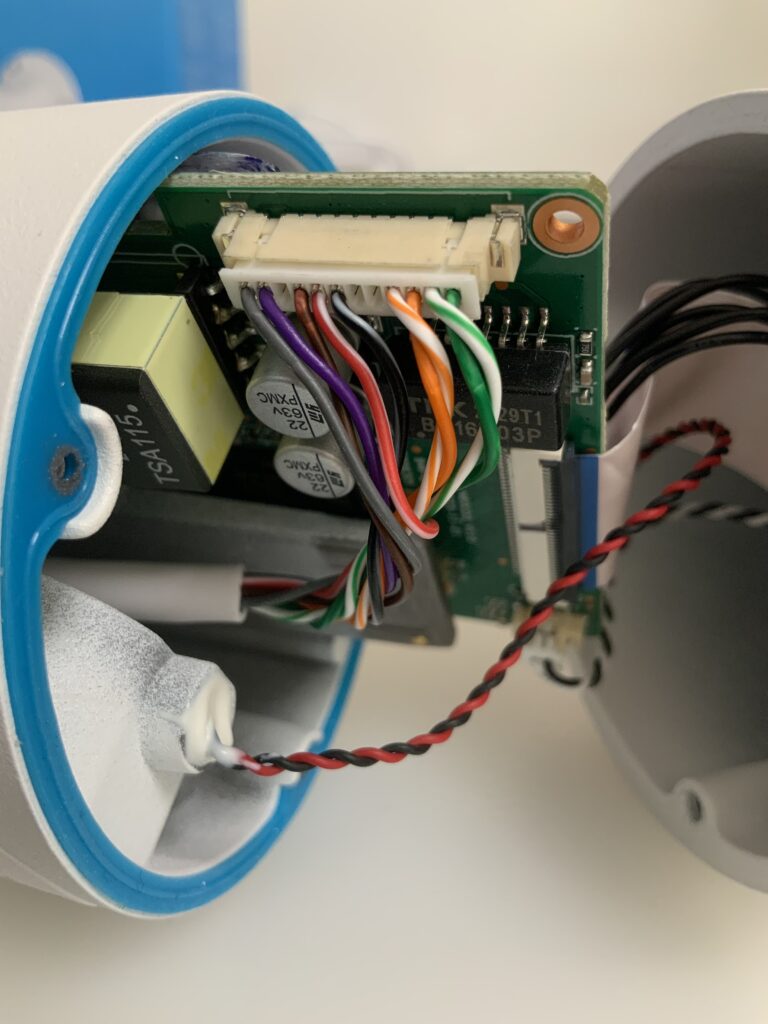
Unfortunately I did not have a 12 pin connector “in stock” but I do have a bunch of 4 pins with hookup cables already crimped in so I used those, they fit just fine. 😊 This way, if I need to, I can always re-fit the original cable without issue. The connectors, both the original and mine are of the JST1.25 type.
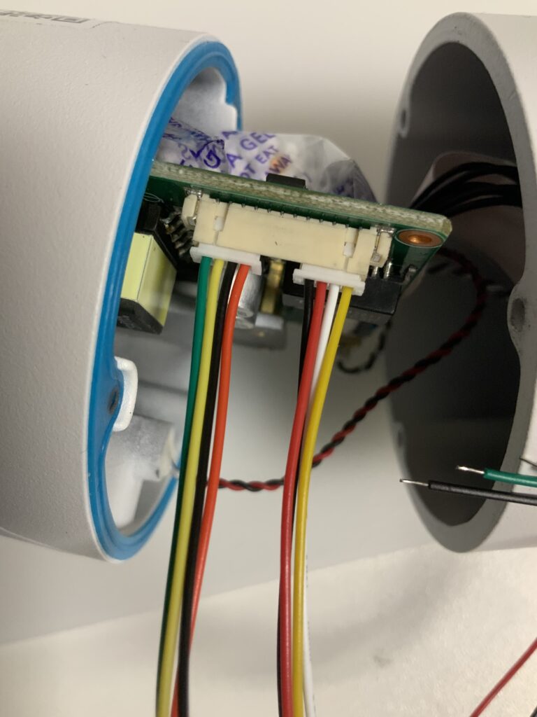
If one looks closely one can see my 2x 4pin connectors don’t cover all default pins in use. In my case that’s deliberate. I don’t need the red and black wires, these connect to the DC power connector on the standard splitter cable.
With that I come to the reason of writing this; to document but also perhaps help others looking for information regarding the makeup of these cables, pin outs etc. I myself had to combine different pieces of information found on Reddit.
12 pin JST1.25 female connector pinout
| pin 1: green | 10/100Mbps ethernet data, pin 6 RJ45 green wire in a standard 568B ethernet cable |
| pin 2: green/white | 10/100Mbps ethernet data, pin 3 RJ45 green/white wire in a standard 568B ethernet cable |
| pin 3: orange | 10/100Mbps ethernet data, pin 2 RJ45 orange wire in a standard 568B ethernet cable |
| pin 4: orange/white | 10/100Mbps ethernet data, pin 1 RJ45 orange/white wire in a standard 568B ethernet cable |
| pin 5: not connected | |
| pin 6: not connected | |
| pin 7: black/white | GND on the Reolink break-out cable DC connector |
| pin 8: red/white | +12V on the Reolink break-out cable DC connector |
| pin 9: brown | Reset (when connected to ground the camera resets) |
| pin 10: not connected | |
| pin 11: purple | ethernet PoE, pin 7 RJ45, brown-white wire in a standard 568B ethernet cable |
| pin 12: grey | ethernet PoE, pin 4 RJ45/blue wire in a standard 568B ethernet cable |
The below schematic I found on Reddit, credits to Pdownes2001 for sharing this!
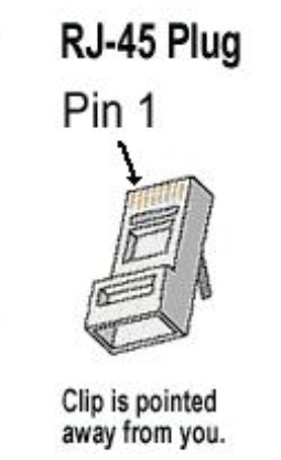
With this it was easy to map the wires to a standard 568B wired RJ-45 connector/ethernet cable (and in my case to the colors I used on the 2x 4p connectors).
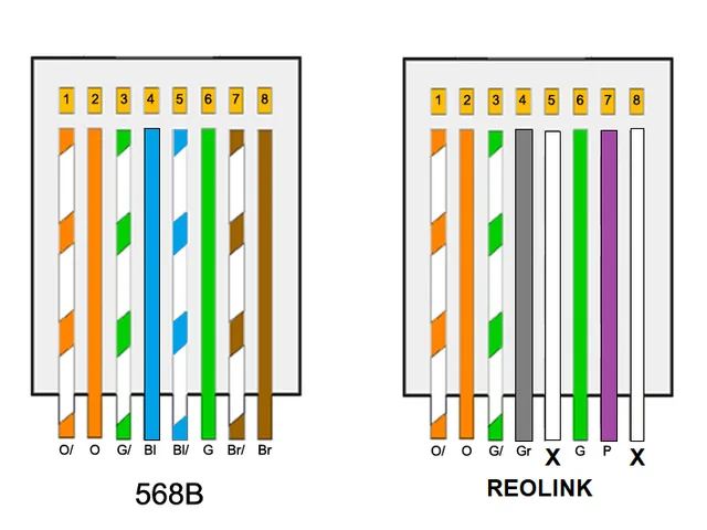
This depicts the RJ45 connector with the connector clip down and you looking in the cable entry, like below. Of course you’ll need an ethernet crimping tool or a RJ45 field connector.